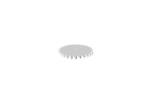
Gears
Create 3D gears with fully configurable tooth geometry. MatterCAD generates proper involute gear profiles that mesh correctly with other gears of the same module and pressure angle.
How to Use
- Add a Gear from the Mechanical tools or Primitives panel
- Set the tooth count and other parameters
- The gear profile is generated automatically
Parameters
Features
- Gear Type - External gear or Rack (straight bar with teeth)
- Height - Thickness of the gear (extrusion height)
- Tooth Count - Number of teeth around the gear (default: 30, range: 4-60)
- Circular Pitch - The arc distance between teeth along the pitch circle (range: 3-30). This determines the overall size.
- Center Hole Diameter - Diameter of the center shaft hole (default: 4mm, set to 0 for no hole). External gears only.
- Outer Edge Width - Width of the edge outside inner teeth
- Inner Gear Tooth Count - Tooth count of the mating internal gear
Advanced
- Pressure Angle - The angle of the tooth contact surface (common values: 14.5, 20, or 25 degrees). All meshing gears must use the same pressure angle.
- Clearance - Minimum gap between the tooth tip and the mating tooth trough
- Backlash - Minimum gap between meshing gear teeth to prevent binding
Gear Data (Read Only)
- Pitch Radius - The radius where gears mesh with each other
- Outer Diameter - The total diameter to the tip of the teeth
Tips
- Two gears will mesh correctly when they have the same Circular Pitch and Pressure Angle
- Use the Pitch Radius values to correctly space meshing gears – the distance between gear centers should equal the sum of their pitch radii
- Add Backlash for 3D printed gears to account for printing tolerances
- For 2D gear profiles (for use with Extrude), see Gear 2D